[GUIDA] Montaggio Sedili Elettrici & Riscaldati!

It has already been explained on the forum how to connect the wires. It will not work until the CAN Bus wires are connected as well. If the car does not have the original installation it is better to connect it to the body computer. It is the closest. After connection, you need to perform the proxy alignment. Mostly a 2-3 day job. No special knowledge is needed, but definitely a tool.
Scusate se riesumo un vecchio thread e per il mio pessimo italiano, sono in Inghilterra cercando di montare i sedili elettrici riscaldati sulla mia Giulietta con sedili manuali riscaldati e volevo solo chiarire.

Una volta collegate la tensione (pin 7) e le 2 masse (pin 6 e 10) devo collegare i cavi CAN (pin 8 e 9) al BC e quindi eseguire un allineamento proxy, è corretto? Inoltre, il pin 8 va al pin 45 o al pin 60 del BC? e lo stesso per il pin 9.

Grazie, questo thread è pieno di informazioni eccellenti
 
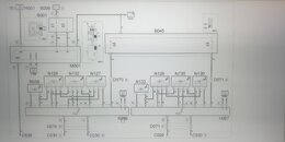
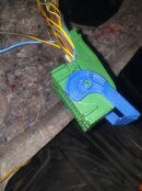
Regarding BC CAN wires - just follow wire colurs.Blue to blue, yellow to the yellow since from electrical drawings is not clear which pin is connected to the 45 or 60.This wires are very thin-it is not possible to make mistake finding them.Also observe picture from original drawing (you can find it on internet).Whatever you do,disconnect battery. I choose connector from picture for CAN connection-F connector on body computer.
 

Allegati

  • 20241206_062710.jpg
    20241206_062710.jpg
    434.7 KB · Visualizzazioni: 13
  • Screenshot_20241206-063222_Gallery.jpg
    Screenshot_20241206-063222_Gallery.jpg
    113.3 KB · Visualizzazioni: 12
Regarding BC CAN wires - just follow wire colors.Blue to blue, yellow to the yellow since from electrical drawings it is not clear which pin is connected to the 45 or 60.This wires are very thin-it is not possible to make a mistake finding them .Also observe picture from original drawing (you can find it on internet).Whatever you do,disconnect battery. I choose connector from picture for CAN connection-F connector on body computer.

okay, thanks for the info, so the green connector in your photo is the F connector, the blue connector on M001 in my photo? do you access this connector from inside the cabin or from the engine bay? and just to confirm, pins 45 and 60 of this connector, yes? sorry for all the questions, thanks for the quick reply :)


1733479447618.png
 
- Informazione Pubblicitaria -
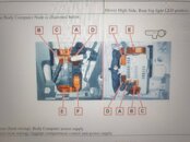
Regarding the connector-see attached photo.Since you are in England,persume that you have steering wheel on right side.If so,connectors arrangement is little bit different ,but from photo you can see which one is F. Once more - right immage on photo is for right placed steernig wheel ,left is for left steering wheel.
Acess is from cabin-below steering wheel-fuse area.
Regarding pins 45&60 -yes they are on this connector.
It will be good to buy generic socket for cable connection below seats-in case that your car do not have original socket.
 

Allegati

  • 17334831079619123445910382493876.jpg
    17334831079619123445910382493876.jpg
    1 MB · Visualizzazioni: 7
Regarding the connector-see attached photo.Since you are in England,persume that you have steering wheel on right side.If so,connectors arrangement is little bit different ,but from photo you can see which one is F. Once more - right immage on photo is for right placed steernig wheel ,left is for left steering wheel.
Acess is from cabin-below steering wheel-fuse area.
Regarding pins 45&60 -yes they are on this connector.
It will be good to buy generic socket for cable connection below seats-in case that your car do not have original socket.
ahhh grazie, il venditore dei sedili originali mi sta inviando i connettori oem che salderò con guaina termorestringente ai nuovi fili per una buona connessione, dovrò però riattaccare i 2 connettori per il BCM. Da dove viene quella grafica per i 2 diversi connettori BC che hai appena mostrato? Grazie
 
Photo is from workshop manual of electrical installations for giulietta 940.
 
X